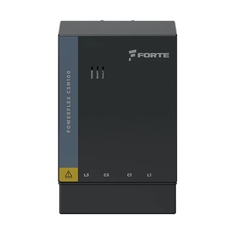
CSM100
Capacitor Switching Module

Combination of Power and Performance — Safe, fast and strong.

Forte CSM100 thyristor modules are robust and durable products, available in two frame sizes rated 50 kvar and 100 kvar at 400V, for systems from 400V to 750V.

3 ms Response Time Up to 750V Up to 100 kvar Microprocessor Controlled Thermistor Protected 24VDC Auxiliary
3 ms Switching Speed
400V – 750V operation
Microprocessor Controlled
Over Temperature Safety
Fault Code Notification
3 ms
Response Time
More precise control, faster switching
750V
Maximum Voltage
400V / 525V / 600V / 690V / 750V
100 kvar
Maximum Power
FSC frame, at 400V
Passive Power Quality

Switching that never
wears out

A contactor closes on a charged capacitor and pays for it — inrush current, welded tips, a service call. CSM100 switches with thyristors instead: no moving contact, nothing to burn, 3 ms from command to conduction. On loads that step hundreds of times a day, that is the difference between a panel you maintain and a panel you forget about.

The series is built in two frame sizes — FSA at 50 kvar and FSC at 100 kvar (at 400V) — and supports 400V, 525V, 600V, 690V and 750V systems.

It looks after itself. Cooling runs on temperature, not on a timer. Five conditions are watched continuously — heatsink above 80 °C, reactor thermostat, NTC sensor failure, control supply below 21.5 V and loss of mains — and each one trips before it becomes damage. A potential-free contact reports the fault to your PLC, and three front-panel LEDs name it before anyone opens a manual.
400V – 750V 3 ms Response Thermistor Protected 24VDC Auxiliary LED Status Display Programmable Fan
Technical DatasheetEN
CSM100 Thyristor Module — Front View
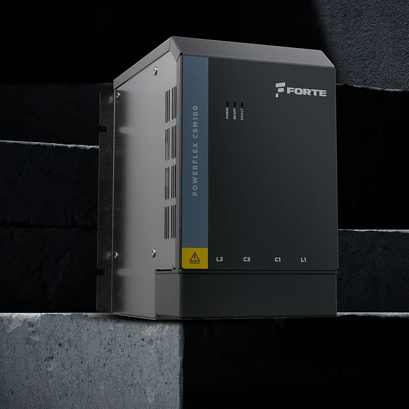
CSM100 Thyristor Module — Side View
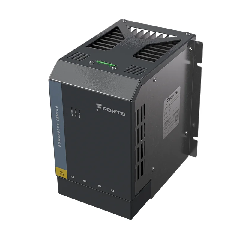
CSM100 Thyristor Module — Detail View
Key Features

What Makes CSM the Right Choice

Robust thyristor switching with microprocessor intelligence, built for the demands of industrial reactive power compensation.

Microprocessor Controlled

Intelligent microprocessor management ensures precise timing, reliable switching and seamless integration with reactive power compensation controllers.

Controlled Fan Support

Programmable fan control lets you set the temperature threshold for activation and deactivation, optimising cooling efficiency and extending component life.

Over Temperature Safety

Built-in thermal protection continuously monitors module temperature and triggers automatic shutdown before critical thresholds are reached, safeguarding thyristors and connected equipment.

Supply Voltage Measurement

Real-time monitoring of supply voltage ensures the module operates within safe limits and provides early warning of abnormal grid conditions.

Fault Code Notification

Diagnostic fault codes enable rapid identification of issues during commissioning and operation, reducing downtime and simplifying maintenance workflows.

Up to 750 Volts

Native support for 400V, 525V, 600V, 690V and 750V voltage levels covers the full range of industrial distribution systems without external step-down transformers.

Thermistor Protected

NTC thermistors provide the most precise temperature measurements. With fast response time, they are the ideal solution in variable temperature environments for reliable thermal monitoring.

Technical Specifications

CSM Series — Full Specification

Complete technical parameters for all three CSM frame sizes. All models share the same control architecture and monitoring features.

Specification FSA — 50 kvar FSC — 100 kvar
Dimensions (w × d × h)155.0 × 201.8 × 189.6 mm155.0 × 201.8 × 243.9 mm
Mounting holes 4 × Ø4151.0 × 173.8 mm151.0 × 223.9 mm
Terminal projection22.4 mm21.7 mm
Weight5.1 kg6.3 kg
Voltage400V / 525V / 600V / 690V / 750V400V / 525V / 600V / 690V / 750V
Maximum Overvoltage+10%+10%
Frequency50 Hz50 Hz
Max. Reactive Power50 kvar (@400V)100 kvar (@400V)
Max. RMS Current75 A145 A
Frame SizeFSAFSC
Auxiliary Supply24VDC24VDC
Start SignalVia external potential free contact
MonitoringVoltage, temperature and operation status via LEDs; Potential free contact (output) for alarm
Display3 LEDs — GREEN: 24 V DC supply OK / YELLOW: module switched on / RED: alarm active
Power CircuitDirect connection 4-pole via bus bar cable lug 50 mm², connection from bottom
Power Dissipation144 W285 W
Conduction loss at maximum RMS current and worst-case junction temperature. Auxiliary supply and snubber losses are not included.
Ordering Code

How the code is built

The type code has six fields. The example below is an FSA module with 400V supply, 50A load capacity and a 24VDC fan.

1CS
10
2B
050
W
21

Colours match each code field to its row below · 1CS is the fixed prefix

Module type field 3
10 Basic w/o Field Bus
Supply voltage field 4
2B 400V 3C 525V 4D 600V 5E 690V 6F 750V
Load capacity field 5
FSA
020 20A040 40A050 50A080 80A
FSC
120 120A150 150A

Load capacity determines the frame size

Fan supply field 6
X Without fan W 24VDC fan, internal supply B 220VAC fan, external supply
Internal designation field 7
21 Fixed index; next version 22, then 23.

Electrical Connection — Incorrect phase connection destroys the module

The CSM100 controls power through its own two-phase connection; one phase is connected directly to the load. The two controlled phase inputs must be connected to the leftmost and rightmost busbars (L1 and L3). Incorrect phase connections to C1 or C3 will destroy the internal protection varistor. The C1 and C3 terminals must be connected to the load.

Control Terminals

T1 – T5 connections

The five-pole control terminal block on the front of the module. All signals are 24VDC.

T1
T2
T3
T4
T5
T1Reactor thermostat overheat alarm input, 24VDC.
Must be shorted with T4 if not used.
T2Alarm output, 24VDC.
T3Start input from the power factor controller, 24VDC.
Must come from the same supply as T4; if not, both supplies must share a common reference point — they cannot be left floating.
T4Power supply 24VDC (+)
T5Power supply 0VDC
Troubleshooting

Read the three front-panel LEDs

Look at the three LEDs, then find the row below. Flashing means equal on and off time.

off on flashing G green · Y yellow · R red
Normal Operation
G
Y
R
Standby
Supply healthy, waiting for the start command
G
Y
R
Running
Thyristors firing — the module is conducting
G
Y
R
Rest period
Duty-cycle rest after continuous operation · flash rate not fixed by the timer
Fault Codes — one fault at a time — the firmware shows the highest priority first
CodeLED patternOn / OffFaultCauseWhat to do
A02priority 1
G
Y
R
0.1 son, then off NTC sensor broken Temperature sensor open circuit or disconnected Check NTC wiring and connector; replace the sensor if defective
A03priority 2
G
Y
R
0.05 son, then off Heatsink over-temperature Heatsink temperature exceeded 80 °C Check the fan, clean the heatsink, reduce load, improve ventilation
A05priority 3
G
Y
R
0.1 son, then off 24 V DC supply fault Control supply dropped below 21.5 V Check the 24 V DC supply, input voltage and wiring
A04priority 4
G
Y
R
0.1 son, then off Reactor over-temperature Reactor thermal switch triggered Check reactor ventilation, reduce load, verify the thermal switch
A01priority 5
G
Y
R
0.1 son, then off Mains not detected No zero crossing on either phase for 60 ms Check the mains supply, fuses and circuit breakers

LED behaviour, thresholds and timings taken from the module firmware (MCS114S00R00) and its 100 µs timer interrupt. 0.1 s on/off = 5 Hz · 0.05 s on/off = 10 Hz.

Ready to specify CSM for your project?

Our engineering team will help you select the correct frame size and voltage configuration based on your facility's reactive power requirements — at no cost before commitment.

← All Passive PQ Products
Documents

Technical documents for this product. Ask for a document still in preparation and we will send it as soon as it is ready.

Technical DatasheetEN Download PDF

Request a Quote — CSM Series

Our engineering team will contact you within 1 business day. Urgent: +90 850 840 64 24

Type code 1CS10 – __ ___ _ 21 Make the three selections below and the order code builds itself.

By submitting this form you agree to be contacted by Forte Teknik A.Ş. Your data will not be shared with third parties.

Secure · Powered by HubSpot CRM · Response within 1 business day