Alarm Vigil

Product Code: 1VGL2-D24S01

40-channel alarm annunciator — two groups of 20 volt-free inputs, 24 V DC, four front keys. Designed & manufactured by Forte R&D — exclusive product.

⬡   Designed & Manufactured by Forte R&D — Exclusive Product   ⬡
Forte R&D — Own IP Product
Passive Power Quality — Monitoring

Intelligent Panel
Health Monitoring

The Forte Alarm Vigil is an exclusive product developed entirely by Forte's R&D team. Designed specifically for use inside GRIDFIX compensation panels, it provides immediate visual and audible feedback on panel health and fault conditions — enabling rapid response and enhanced operational safety.

Unlike generic indicators, the Alarm Vigil is engineered to understand the specific fault states of thyristor-switched compensation systems, delivering actionable diagnostics rather than simple on/off alerts. Every installation provides your maintenance team with real-time visibility into panel status without opening the cabinet.
Technical DatasheetEN
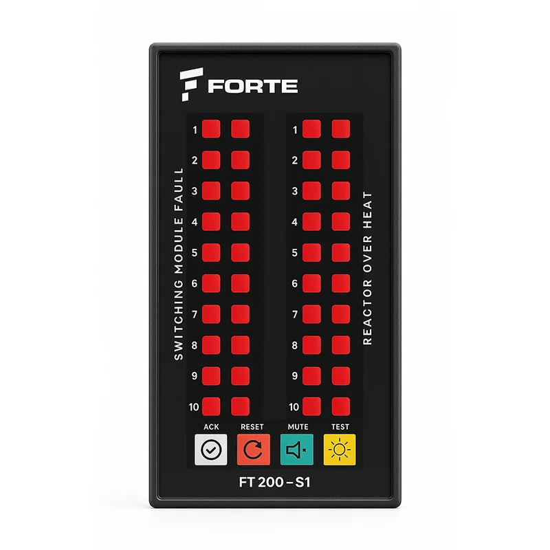
Alarm Vigil — Front View
Alarm Vigil — Detail View
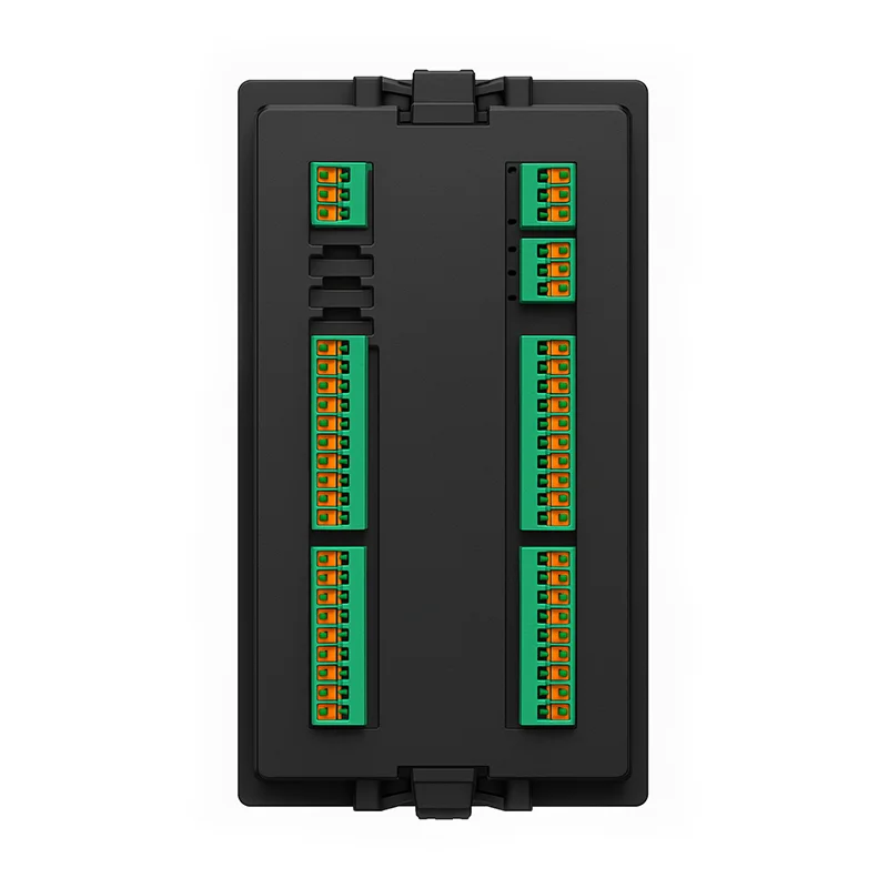
Alarm Vigil — Rear View
Key Features

Built for Operational Safety & Speed

Every feature is designed around one goal: getting the right information to the right person as fast as possible — so faults are resolved before they become failures.

Instant Fault Indication

The moment a fault condition occurs in the compensation panel, the Alarm Vigil provides immediate visual and audible indication — no delay, no guesswork. Maintenance teams can locate the fault before equipment is damaged.

Multi-Channel Monitoring

Simultaneously monitors multiple fault channels within the panel. Each channel provides independent status indication, allowing technicians to identify exactly which module or stage has triggered a fault condition.

Visual LED Display

High-visibility LED indicators provide clear status at a glance — even from a distance. Colour-coded states (normal, warning, fault) allow instant interpretation without reading displays or using diagnostic tools.

Audible Alarm Output

Integrated audible alarm ensures fault conditions are not missed in noisy industrial environments. The alarm can be acknowledged and silenced by operators while the visual indicator remains active until the fault is resolved.

Panel-Level Integration

Designed to integrate directly into GRIDFIX compensation panels. Wiring, mounting, and signal connections are standardised for fast installation. Compatible with CSM100 thyristor module fault outputs.

Reduced Maintenance Time

By pinpointing the fault location instantly, the Alarm Vigil eliminates the time spent diagnosing which module has failed. Combined with GRIDFIX hot-swap capability, faults can be resolved in minutes rather than hours.

Channel Map

Two groups, forty channels

The forty inputs are labelled in two groups. The inputs are volt-free contacts — what you wire into them is up to you; the group names are printed on the front and rear labels.

SWITCHING MODULE FAULT
20 channels
inputs 1 – 20

One channel per switching module. The module’s own fault contact closes and the matching indicator lights — the operator reads a number, not a symptom.

REACTOR OVER HEAT
20 channels
inputs 21 – 40

One channel per detuned reactor. The thermal switch inside the winding closes long before the reactor is damaged, and the step can be shed before anything is lost.

There is no 1–40 sequence on the device — there are two sets of 1–20. Internally the hardware and firmware keep one flat sequence of forty (SWITCHING MODULE FAULT 1–20 are channels 1–20; REACTOR OVER HEAT 1–20 are channels 21–40), but that sequence is not marked on the device and is not used in wiring schedules. In a manual, a fieldbus register map or a terminal marking, only the group name and number may be used.

Annunciation Sequence

The device latches

An alarm that has appeared stays on the front until an operator clears it — even if the fault itself has gone. A flashing indicator means nobody has acknowledged it yet. On this device MUTE and ACK are separate actions: one silences the horn, the other steadies the indicator.

Everything normalno alarm presentAlarm appearsinput contact closesOperator presses MUTEthe horn is silencedOperator presses ACKthe alarm is acknowledgedInput clears + RESETthe record is cleared
Indicator offflashingstill flashingsteadyoff
Horn relay RELEASEDPICKED UPRELEASEDRELEASEDRELEASED
Common alarm relay RELEASEDPICKED UPPICKED UPPICKED UPRELEASED
Front Panel Keys

Four keys

ACK

Steadies every flashing indicator. The horn is not affected — use MUTE for that.

RESET

Clears the record. A channel whose input is still active latches again at once, but comes back steady and does not sound the horn a second time.

MUTE

Releases the horn relay. Indicators keep flashing and the common alarm relay is unchanged.

TEST

Lights every indicator while the key is held. Relay outputs are not affected.

MUTE and ACK do different things

MUTE silences the horn. ACK steadies the indicator. Neither does the other — this device needs both keys. On an acknowledged alarm the common alarm relay stays picked up, so an alarm that has been seen cannot be forgotten.

Technical Data

Technical Specifications

The values below are taken from the Rev A datasheet. The full datasheet can be downloaded from the button at the top of this page or in the Documents section below.

ParameterSpecification
Function40-channel alarm annunciator with first-out indication
Order code1VGL2-D24S01
MountingPanel mounting, front bezel with rear clamps
Inputs
Channels40 — two groups of 20 volt-free inputs
Group namesSWITCHING MODULE FAULT (1–20) · REACTOR OVER HEAT (1–20)
Input typeVolt-free contact, optocoupler-coupled
Input current10.3 mA at 24 V DC · 2.2 kΩ series · LED VF 1.3 V
CommonSupply (−) — all inputs share one common
Wiring rule(+) → external contact → IN n
Input filterRC per channel, plus a 30 ms stability requirement in firmware — an input must hold its state for 30 ms before the channel latches
Outputs
Relays2
FAULT relayChangeover, NO / NC / C — picks up while any alarm is latched
Horn relay (terminal LAMP)NO / C — picks up when a channel latches a new alarm; released by MUTE or RESET. ACK does not release it
Contact formSPDT (1 form C), silver alloy
Contact rating1 A rated · 2 A max. switching current
Max. switching voltage120 V AC / 60 V DC — 230 V AC must not be switched
Supply
Auxiliary supply24 V DC
ProtectionReverse-polarity diode, 470 µF reservoir
Indication and control
Indicators40 red LEDs in two groups of 20
KeysACK · RESET · MUTE · TEST
Flash rate, unacknowledged2 s on / 2 s off
Connection and enclosure
TerminalsPluggable screw terminals, 3.81 mm pitch, one pole per channel
Front bezel144.2 × 72.1 mm (landscape)
Body cross-section129.2 × 61.3 mm — must pass through the panel opening
Panel cut-out129.2 × 65.3 mm
Body flange139.4 × 72.2 mm — bears on the rear face of the panel
Projection in front of panel6.6 mm, of which 3.1 mm is the bezel face
Depth behind the panel61.3 mm — terminals and wiring are additional
Overall depth67.9 mm
Ambient temperature−20 °C … +50 °C
Degree of protectionIP55 front · IP20 behind the panel
Weight260 g
System Integration

Works With the Full GRIDFIX Ecosystem

The Alarm Vigil is designed as an integral part of the GRIDFIX passive compensation system — not an add-on afterthought.

GRIDFIX Compensation Panel
🔲
CSM100 Thyristor Module
📊
Reactive Power Control Relay
🔋
Power Capacitors & Reactors
Why It Matters

From fault to fix — in minutes, not hours

Without a dedicated annunciator, identifying a fault in a multi-stage compensation panel requires opening the cabinet, checking each module individually, and running diagnostics — a process that can take 30–60 minutes or more. With the Forte Alarm Vigil, the fault channel is immediately visible from outside the cabinet. Combined with GRIDFIX hot-swap modularity, total fault-to-fix time drops from hours to minutes.

Without Alarm Vigil 30–60 min
With Forte Alarm Vigil < 5 min

Fault identification time, typical GRIDFIX panel

Connections

Rear terminal arrangement

The layout below is the terminal side, as the rear label reads it. A terminal is identified the way it is marked on the device — group name and number.

REAR VIEW — the terminal side
REACTOR OVER HEAT
20191817161514131211
10987654321
24 V DC
+
ALARM VIGIL1VGL2-D24S01
inputs: (+) → contact → IN · common = supply (−)
24 V DC · 2 relay outputs · 2 × 20 inputs
20191817161514131211
10987654321
SWITCHING MODULE FAULT
CNCNO
FAULT
CNO
LAMP
Terminal groupPolesMarkingFunction
SWITCHING MODULE FAULT201 … 20Alarm inputs, one pole each
REACTOR OVER HEAT201 … 20Alarm inputs, one pole each
24 V DC2− +Auxiliary supply
FAULT3C NC NOChangeover — picks up while any alarm is latched
LAMP2C NOHorn output — picks up on a new alarm, released by MUTE or RESET

Wiring rule

All forty inputs share one common return — the supply negative. Drive the contacts from this device’s own 24 V supply. Feeding them from a second supply would join two systems through that common return.

Service note. The connector references CN3…CN9 printed on the boards are for service only; they are not used in wiring schedules.

Ordering

One product, one code

There are no variants, no options and no code segments to choose — the device is always supplied in the same configuration.

1VGL2-D24S01
ALARM VIGIL · 2 × 20 channel alarm annunciator, 24 V DC, panel mounting
DeviceAnnunciator in its panel-mounting enclosure, front bezel fitted
TerminalsAll plug-in terminal blocks fitted: 4 × 10-pole inputs, 24 V DC, two relay outputs
LabelsFront and rear labels applied; identification label with serial number on the side wall

The serial number is on the side-wall label, in plain text and as a barcode. Quote it in any correspondence about a particular unit: the type code identifies the product, the serial number identifies the unit.

Interested in the Alarm Vigil?

Available as part of a complete GRIDFIX panel or as a standalone monitoring upgrade for existing compensation systems. Contact our engineering team for availability and pricing.

Documents

Technical documents for this product. Ask for a document still in preparation and we will send it as soon as it is ready.

Technical DatasheetEN Download PDF Technical DatasheetTR Download PDF

Request a quote for ALARM VIGIL

Our engineering team will get back to you within 1 business day. Urgent: +90 850 840 64 24

Type code 1VGL2-D24S01 One product, one code — no variants or options to choose.

By submitting this form you agree to be contacted by Forte Teknik A.Ş. Your data is stored in our CRM (HubSpot, EU data centre) and is not sold. See the Privacy & Data Protection Notice.

🔒 Secure · Powered by HubSpot CRM · Response within 1 business day