GRIDCAP
Film Capacitors

Self-healing metalized polypropylene film capacitors designed for power factor correction in industrial and commercial installations. 5 to 40 kvar, 230V to 900V. Available in Delta (D), Star (Y) and Parallel (P) connections. Built to IEC 60831-1 & -2.

230V – 900V 5 – 40 kvar Self-healing MKP Built to IEC 60831-1 & -2 RoHS Compliant
Self-healing technology
5 – 40 kvar range
230V to 900V
IP20 indoor rated
Expected life >100,000 hrs
Division 01 — Passive Power Quality

Reliable film capacitors
for PFC systems

The GRIDCAP series consists of self-healing metalized polypropylene film (MKP) capacitors manufactured to IEC 60831-1&2 standards. Designed specifically for power factor correction panels, GRIDCAP capacitors work in conjunction with GRIDTUNE detuned reactors and CSM100 thyristor modules to form complete GRIDFIX compensation systems.

With nominal voltages from 230V to 900V and power ratings from 5 to 40 kvar, GRIDCAP covers all standard industrial voltage levels. Available in three connection types — Delta (D) for 3-phase systems, Star/Wye (Y) for 800V and 900V configurations, and Parallel (P) for single-phase or 230/250V applications.

Self-healing technology ensures continued operation after minor dielectric breakdowns. Epoxy resin filling provides moisture and vibration resistance. RoHS compliant, mercury-free, non-PCB construction meets all current environmental regulations.
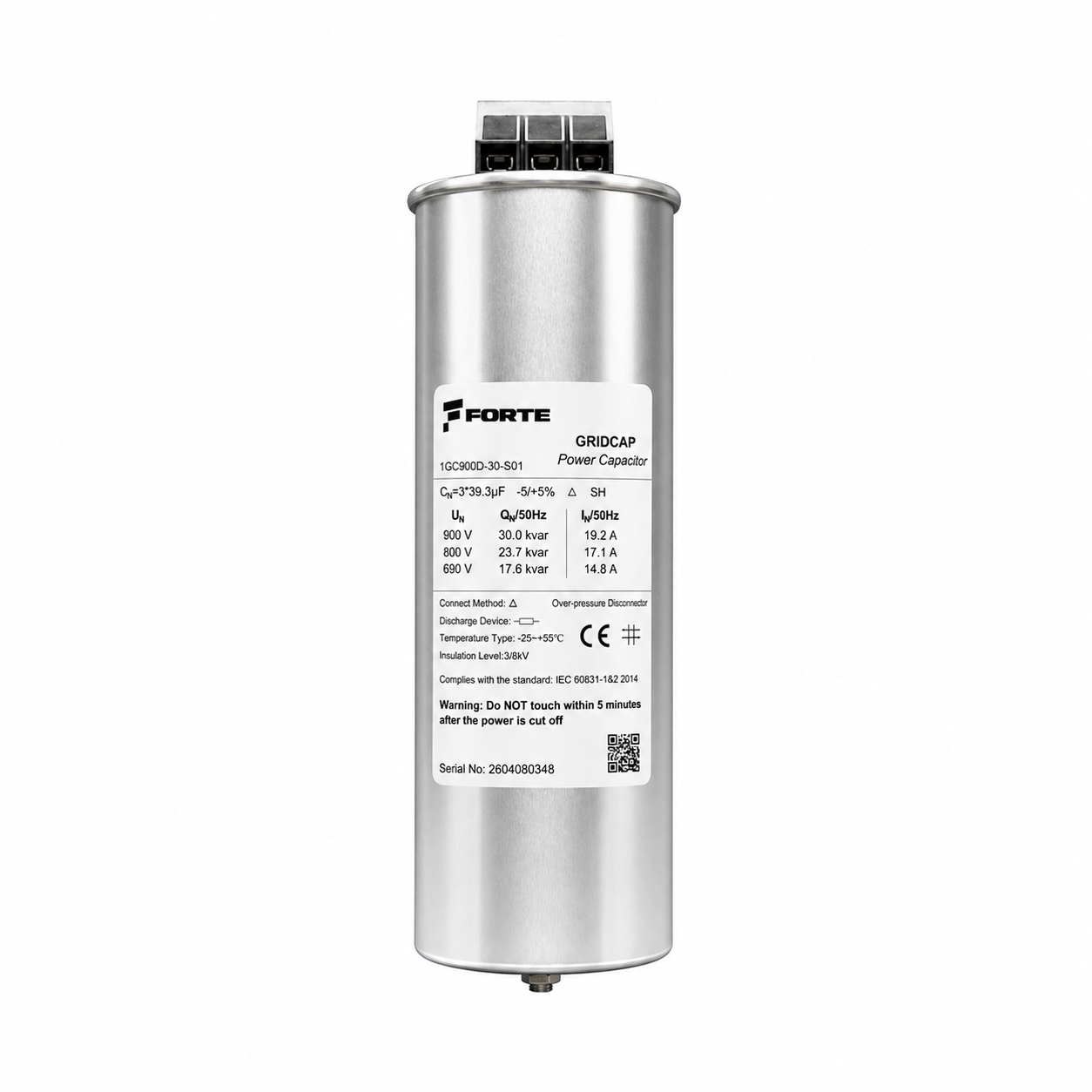
Self-healing MKP Built to IEC 60831-1 & -2 230V – 900V RoHS Compliant Epoxy filled
Technical BrochureEN
Forte GRIDCAP Film Capacitor
900V
Maximum
nominal voltage
40 kvar
Maximum
power rating
>100,000 hrs
Expected life
at ≤40°C
±5%
Capacitance
tolerance
Technical Specifications

GRIDCAP — Full Specification

All parameters for Forte GRIDCAP film capacitors. Standard range covers 5 to 40 kvar at 230–900V.

ParameterSpecification
ProductForte GRIDCAP Series — Film Capacitor
DielectricSelf-healing metalized polypropylene film (MKP)
Filling materialEpoxy resin
Nominal voltage VN230 … 900 V AC
Nominal frequency50 / 60 Hz
Capacitance tolerance±5%
Nominal output QN5 … 40 kvar
Insulation level3 / 8 kV
Connection typesD (Delta / 3-phase) · Y (Star / 3-phase) · P (Parallel / 1-phase)
Dielectric losses (with reactor)0.5 W/kvar (dielectric) · 0.7 W/kvar incl. discharge resistor
Dielectric losses (without reactor)0.2 W/kvar (dielectric) · 0.5 W/kvar incl. discharge resistor
Max. AC voltage (Vmax)VN +10% up to 8h/day; VN +15% up to 30min/day; VN +20% up to 5min/day; VN +30% up to 1min/day
Max. AC current (Imax)1.1 × IN (continuous · short-time 1.5 × IN, max. 1 min/day on average)
Max. inrush current200 × IN (millisecond-scale withstand limit — non-normal, infrequent)
Max. switchings/year5,000 (thyristor zero-crossing switching · 1,000/year with AC contactor)
Test voltage, terminal–case4,000 V / 10 s
TerminalsBolted terminal block, IP20 — max. cable 25 mm²
MountingM12 or M16 bottom bolt — M8/M10 connection bolts
Mounting positionUpright / inverted / horizontal
EnclosureIP20, indoor installation
Ambient temperature−25°C / +55°C
Max. hotspot temp.+65 °C (case surface · ambient +55 °C)
Hotspot rise above ambient≤ 10 K (above ambient)
Temperature category−25/D (IEC 60831-1)
Storage temperature−25°C to +55°C
CoolingNatural air cooling
Humidity< 85% (non condensing)
Max. altitude< 2,000 m
Max. short circuit≤ 10 kA (with current-limiting fuse · withstand ≤ 5 ms)
Over-pressure operating point0.2 MPa
Can expansion on operation30 mm (when the over-pressure disconnector operates)
Free space above unit≥ 40 mm (inside the panel)
Design standardBuilt to IEC 60831-1 & -2 (2014)
Type test certificateR 50708806 0001
ComplianceRoHS compliant · Mercury free · Non-PCB · Toxic heavy metal free
End-of-life criterionMeasured capacitance ≤ 70 % of rated value
Shelf life≤ 18 months (dry, dust-free storage)
Quality systemISO 9001 — current certificate available
Routine testing100 % routine test — capacitance · loss · case withstand · inter-electrode withstand
Warranty12 months (subject to warranty conditions)

Safety — stored energy

A power capacitor holds a dangerous charge after disconnection. Wait at least 5 minutes after switching off and verify zero voltage before touching the terminals. Short-circuit and earth the terminals before any work.

GRIDCAP has an internal discharge device that brings the residual voltage to ≤ 75 V within 3 minutes, per IEC 60831-1. The 5-minute figure above is the safety margin used on the product label. Installation and service by qualified personnel only.

Leave room above the unit. When the over-pressure disconnector operates the can expands by up to 30 mm. Leave at least 40 mm free space above each capacitor inside the panel.

Expected Operating Life

Temperature vs. Service Life

Hotspot temperature directly affects capacitor life. Lower temperatures significantly extend service life.

Hotspot TemperatureExpected Life
≤ 40°C≥ 100,000 hours
45°C≈ 70,000 hours
50°C≈ 50,000 hours
55°C≈ 35,000 hours
Note: Ensure adequate ventilation inside PFC panels. Every 10°C reduction in hotspot temperature approximately doubles expected capacitor life.
Selection Guide

Voltage & Connection Selection Guide

Choose the correct voltage and connection type based on your system configuration.

Voltage CodeNominal VoltageConnectionTypical Application
230230VP (Parallel)Single-phase, 230V systems
250250VP (Parallel)Single-phase, 250V systems
440440VD (Delta)Standard 400V industrial (most common)
480480VD (Delta)480V export / US standard
525525VD (Delta)Use with p=7% detuned reactor at 400V
800800VY (Star)Use with p=14% detuned reactor at 400V
900900VY (Star)Use with p=7% detuned reactor at 525V
Note: When using detuned reactors, the capacitor voltage must be higher than the network voltage to compensate for the voltage drop across the reactor. 525V capacitors are standard for p=7% detuned systems at 400V networks.
Product Catalog — 440V Delta

440V Delta — Standard Industrial

Most common selection for 400V industrial installations without detuned reactors.

kvarIN (A) 50HzDimensions d×h (mm)Forte Code
56.676×2401GC440D-5-S01
1013.176×2401GC440D-10-S01
1519.786×2801GC440D-15-S01
2026.296×2801GC440D-20-S01
2532.8106×2801GC440D-25-S01
3039.4116×2801GC440D-30-S01
Product Catalog — 525V Delta

525V Delta — For p=7% Detuned Systems

Standard selection when paired with GRIDTUNE p=7% detuned reactors on 400V networks.

kvarIN (A) 50HzDimensions d×h (mm)Forte Code
55.576×2401GC525D-5-S01
1011.076×2801GC525D-10-S01
1516.586×2801GC525D-15-S01
1819.896×2801GC525D-18-S01
2022.096×2801GC525D-20-S01
2527.5106×2801GC525D-25-S01
3033.0116×2801GC525D-30-S01
4044.0136×2901GC525D-40-S01
Key Features

What Makes GRIDCAP the Right Choice

Engineered for reliability, efficiency and seamless integration into power factor correction panels.

Self-Healing Technology

Metalized polypropylene film automatically isolates micro-faults, maintaining capacitor integrity and extending operational life.

Wide Voltage Range

From 230V single-phase to 900V star-connected configurations, GRIDCAP covers every standard voltage level in industrial PFC.

Three Connection Types

Delta (D), Star/Wye (Y) and Parallel (P) connections available to match any system topology.

Long Operating Life

Over 100,000 hours expected life at hotspot temperatures ≤40°C. Self-healing extends service intervals.

Environmental Compliance

RoHS compliant, mercury-free, non-PCB, toxic heavy metal free. Meets all current environmental regulations.

GRIDFIX Integration

Designed to work with GRIDTUNE detuned reactors and CSM100 thyristor modules in complete GRIDFIX compensation panels.

Applications

Where GRIDCAP Capacitors Are Used

Film capacitors are the core component of every power factor correction system.

GRIDFIX Compensation Panels

Primary application in Forte GRIDFIX thyristor-switched modular panels.

🏭

Industrial PFC Systems

Power factor correction for motors, pumps, compressors and general industrial loads.

🏪

Commercial Buildings

HVAC, elevator and lighting systems in offices, hospitals and shopping centers.

Renewable Energy

Auxiliary power factor correction for wind and solar plant electrical systems.

Motor Control Centers

Capacitor banks integrated into MCC for localized PFC.

🏯

Utility Distribution

LV distribution network power factor improvement.

Ordering Code

How the code is built

A GRIDCAP code has four fields. Example: 440V, Delta connection, 25 kvar.

1GC
440
D
25
S01

Colours match each code field to its row below · 1GC is the fixed prefix · 1GC440D-25-S01

Nominal voltagefield 2
230 V250 V440 V480 V525 V800 V900 V
Connection typefield 3
D Delta (3-phase)Y Star (3-phase)P Parallel (1-phase)

800V and 900V models are Star (Y) connected — choosing the voltage fixes the connection.

Nominal outputfield 4
5 kvar10 kvar15 kvar18 kvar20 kvar25 kvar30 kvar40 kvar
Seriesfield 5
S01

Production / supply generation. A new generation becomes S02; the customer code stays the same.

Valid Combinations

Which output exists at which voltage

Not every voltage is made in every output. The table below lists all 31 codes in production.

Voltage5 kvar10 kvar15 kvar18 kvar20 kvar25 kvar30 kvar40 kvar
230 VP
250 VP
440 VD
480 VD
525 VD
800 VY
900 VY

All ratings are built to IEC 60831-1 & -2 (2014). Type test certificate: R 50708806 0001.

Need help selecting the right capacitor?

Our engineering team will recommend the optimal voltage rating, connection type and power rating based on your network analysis and compensation requirements.

Documents

Technical documents for this product. Ask for a document still in preparation and we will send it as soon as it is ready.

Technical BrochureEN Download PDF Technical BrochureTR Download PDF

Request a Quote — GRIDCAP Capacitors

Our engineering team will contact you within 1 business day. Urgent: +90 850 840 64 24

Order code 1GC____-__-S01 Pick a voltage and an output; the code builds itself.

By submitting this form you agree to be contacted by Forte Teknik A.Ş. Your data will not be shared with third parties.

Secure · Powered by HubSpot CRM · Response within 1 business day